Toyota 4Runner: Disassembly
DISASSEMBLY
CAUTION / NOTICE / HINT
HINT:
- Use the same procedure for the RH and LH sides.
- The procedure listed below is for the LH side.
PROCEDURE
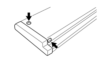
1. REMOVE STEP PLATE COVER LH
|
(a) Remove the 2 screws and step plate cover LH. |
|
2. REMOVE STEP PLATE COVER RH
HINT:
Use the same procedure as described for the step plate cover LH.
3. REMOVE SIDE AUTO STEP MOTOR ASSEMBLY
|
(a) Disengage the 4 clamps. |
|

|
(b) Remove the bolt. |
|

(c) Using a 6 mm hexagon wrench, remove the 3 hexagon bolts and side auto step motor assembly.
4. REMOVE FLOOR SIDE SILL STAY
(a) Remove the 6 bolts and floor side sill stay.

 Removal
REMOVAL
CAUTION / NOTICE / HINT
HINT:
Use the same procedure for the RH and LH sides.
The procedure listed below is for the LH side.
PROCEDURE
1. REMOVE ROCKER PANEL MOULDING (w ...
 Inspection
INSPECTION
PROCEDURE
1. INSPECT SIDE AUTO STEP MOTOR ASSEMBLY
(a) Check that the motor gear rotates smoothly as follows.
NOTICE:
Do not apply positive (+) battery voltage to any te ...
Other materials about Toyota 4Runner:
Removal
REMOVAL
PROCEDURE
1. DISCONNECT CABLE FROM NEGATIVE BATTERY TERMINAL
NOTICE:
When disconnecting the cable, some systems need to be initialized after the cable
is reconnected (See page ).
2. REMOVE NO. 1 ENGINE UNDER COVER SUB-ASSEMBLY
3. REMOVE REA ...
GPS Antenna Connection Malfunction(short) (B15C0,B15C1)
DESCRIPTION
These DTCs are stored when a malfunction occurs in the navigation antenna assembly.
DTC No.
DTC Detection Condition
Trouble Area
B15C0
Navigation antenna error
Nav ...

0.0283