Toyota 4Runner: Disassembly
DISASSEMBLY
PROCEDURE
1. REMOVE RADIATOR GRILLE
.gif)
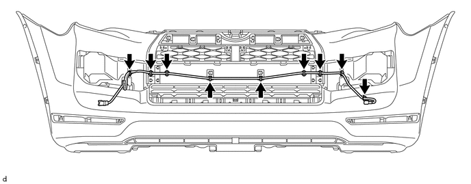
2. REMOVE NO. 2 ENGINE ROOM WIRE
(a) Disconnect each connector.
(b) Detach the 9 clamps to remove the No. 2 engine room wire.
3. REMOVE NO. 1 ULTRASONIC SENSOR
4. REMOVE ULTRASONIC SENSOR CLIP
5. REMOVE NO. 2 ULTRASONIC SENSOR RETAINER
6. REMOVE FRONT BUMPER EXTENSION MOUNTING BRACKET (w/ License Plate Bracket)
|
(a) Remove the 2 screws and front bumper extension mounting bracket. |
|

7. REMOVE FRONT BUMPER SIDE MOULDING LH
|
(a) Remove the 2 outside moulding retainers. |
|

(b) Detach the claw to remove the front bumper side moulding LH.
8. REMOVE FRONT BUMPER SIDE MOULDING RH
HINT:
Use the same procedure as for the LH side.
9. REMOVE FRONT BUMPER LOWER SIDE SUPPORT LH
|
(a) Remove the 2 clips. |
|

(b) Detach the 5 claws to remove the front bumper lower side support LH.
10. REMOVE FRONT BUMPER LOWER SIDE SUPPORT RH
HINT:
Use the same procedure as for the LH side.
11. REMOVE NO. 2 RADIATOR GRILLE MOULDING
|
(a) Remove the 2 outside moulding retainers and 4 screws. |
|

|
(b) Detach the 4 claws to remove the No. 2 radiator grille moulding. |
|

12. REMOVE FRONT BUMPER SIDE MOULDING SUB-ASSEMBLY LH
|
(a) Remove the 3 outside moulding retainers. |
|

(b) Remove the 2 screws.
(c) Detach the 2 claws and guide to remove the front bumper side moulding sub-assembly LH.
13. REMOVE FRONT BUMPER SIDE MOULDING SUB-ASSEMBLY RH
HINT:
Use the same procedure as for the LH side.
14. REMOVE FRONT BUMPER MOULDING SUB-ASSEMBLY
|
(a) Remove the 4 screws. |
|

|
(b) Remove the 15 outside moulding retainers. |
|

|
(c) Detach the 12 guides and 4 claws to remove the front bumper moulding sub-assembly. |
|

15. REMOVE FOG LIGHT ASSEMBLY LH
16. REMOVE FOG LIGHT ASSEMBLY RH
HINT:
Use the same procedure as for the LH side.
 Removal
REMOVAL
PROCEDURE
1. REMOVE UPPER RADIATOR SUPPORT SEAL
2. REMOVE FRONT BUMPER COVER
(a) Put protective tape around the front bumper cover.
(b) Remove the 3 bolts, 10 screws and 6 clips.
(c) ...
 Reassembly
REASSEMBLY
PROCEDURE
1. INSTALL FOG LIGHT ASSEMBLY LH
2. INSTALL FOG LIGHT ASSEMBLY RH
HINT:
Use the same procedure as for the LH side.
3. INSTALL FRONT BUMPER MOULDING SUB-ASSEMBLY
(a) Atta ...
Other materials about Toyota 4Runner:
Selecting modes
Press the “ON/OFF” switch.
All the mode indicators will come on and then go off except the indicator for
the present mode. The applicable road conditions will be displayed on the
accessory meter.
Turn the dial to select the desired mode.
The ind ...
Front Airbag Sensor RH Malfunction (B1610/13)
DESCRIPTION
The front airbag sensor RH consists of the diagnostic circuit and frontal deceleration
sensor, etc.
If the center airbag sensor receives signals from the frontal deceleration sensor,
it determines whether the SRS should be activated.
DTC B16 ...

0.0075