Toyota 4Runner: Installation
INSTALLATION
PROCEDURE
1. INSTALL CENTER CONTROL ABSORBER BRACKET LH
(a) Install the center control absorber bracket with the 2 bolts.
Torque:
29 N·m {296 kgf·cm, 21 ft·lbf}
2. INSTALL CENTER CONTROL ABSORBER BRACKET RH
HINT:
Use the same procedure described for the LH side.
3. INSTALL CENTER CONTROL ABSORBER ASSEMBLY LH
|
(a) Install the center control absorber assembly with the 3 nuts. Torque: 29 N·m {296 kgf·cm, 21 ft·lbf} |
|
.png)
|
(b) Connect the tube to the 2 clamps. |
|
.png)
|
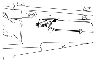
(c) Install the bracket with the bolt. Torque: 29 N·m {296 kgf·cm, 21 ft·lbf} |
|
.png)
(d) While using a wrench to hold the bracket, connect the joint.
Torque:
25 N·m {255 kgf·cm, 18 ft·lbf}
HINT:
For the joint that connects supplied parts, tighten the joint while checking the gap spacing shown in the illustration.

Standard clearance:
1 mm (0.0394 in.)
4. INSTALL CENTER CONTROL ABSORBER ASSEMBLY RH
HINT:
Use the same procedure described for the LH side.
5. INSTALL NO. 1 CENTER CONTROL ABSORBER TUBE LH
|
(a) Install a new No. 1 center control absorber tube with the bolt. Torque: 29 N·m {296 kgf·cm, 21 ft·lbf} |
|
(b) While using a wrench to hold the center control absorber assembly, connect the joint.
.png)
Torque:
25 N·m {255 kgf·cm, 18 ft·lbf}
HINT:
For the joint that connects supplied tubes, tighten the joint while checking the gap spacing shown in the illustration.
Standard clearance:
1 mm (0.0394 in.)
(c) Pass the center control absorber tube between the body and frame.
|
(d) Attach the 2 clamps. |
|
.png)
(e) While using a wrench to hold the bracket, connect the joint.

Torque:
25 N·m {255 kgf·cm, 18 ft·lbf}
HINT:
For the joint that connects supplied tubes, tighten the joint while checking the gap spacing shown in the illustration.
Standard clearance:
1 mm (0.0394 in.)
(f) While using a wrench to hold the bracket, connect the joint.
.png)
Torque:
25 N·m {255 kgf·cm, 18 ft·lbf}
HINT:
For the joint that connects the supplied tubes, tighten the joint while checking the gap spacing shown in the illustration.
Standard clearance:
1 mm (0.0394 in.)
6. INSTALL NO. 1 CENTER CONTROL ABSORBER TUBE RH
HINT:
Use the same procedure described for the LH side.
7. INSTALL TUBE PROTECTOR LH
|
(a) Install the tube protector LH with the bolt. Torque: 29 N·m {296 kgf·cm, 21 ft·lbf} |
|
.png)
8. INSTALL TUBE PROTECTOR RH
HINT:
Use the same procedure described for the LH side.
9. INSTALL FRONT WHEEL
.gif)
10. INSTALL REAR WHEEL
11. INSPECT FOR FLUID LEAK
 Removal
REMOVAL
CAUTION / NOTICE / HINT
NOTICE:
Be sure to read PRECAUTION before performing this procedure (See page
).
PROCEDURE
1. REMOVE FRONT WHEEL
2. REMOVE REAR WHEEL
3. REMOVE CENTER CONTROL ...
 Disposal
DISPOSAL
PROCEDURE
1. DISPOSE OF CENTER CONTROL ABSORBER ASSEMBLY LH
(a) Using a drill, make a hole in the cylinder as shown in the illustration
to discharge the gas inside.
...
Other materials about Toyota 4Runner:
Evaporator Temperature Sensor Circuit (B1413)
DESCRIPTION
The No. 1 cooler thermistor is installed on the evaporator in the air conditioning
unit to detect the temperature of the cooled air that has passed through the evaporator
and control the air conditioning. It sends appropriate signals to the No ...
Dtc Check / Clear
DTC CHECK / CLEAR
1. CHECK DTC
(a) Turn the ignition switch off.
(b) Connect the Techstream to the DLC3.
(c) Turn the ignition switch to ON.
(d) Turn the Techstream on.
(e) Enter the following menus: Chassis / PPS / Trouble codes.
(f) Read the DTCs foll ...

0.0274