Toyota 4Runner: Rear No. 1 Seat Assembly(for 60/40 Split Slide Walk-in Seat Type Lh Side)
Components
COMPONENTS
ILLUSTRATION

ILLUSTRATION

ILLUSTRATION

ILLUSTRATION

ILLUSTRATION

ILLUSTRATION

Removal
REMOVAL
CAUTION / NOTICE / HINT
CAUTION:
Wear protective gloves. Sharp areas on the parts may injure your hands.
PROCEDURE
1. REMOVE REAR SEAT HEADREST ASSEMBLY
(a) Remove the headrest.
2. REMOVE REAR SEAT TRACK INNER BRACKET COVER

(a) Using a moulding remover, detach the 2 claws and guide, and then remove the cover.
3. REMOVE REAR SEAT TRACK OUTER BRACKET COVER

(a) Using a moulding remover, detach the 2 claws.
(b) Move the cover in the direction of the arrow to detach the 2 guides, and then remove the cover.
4. REMOVE SEAT TRACK INNER BRACKET COVER LH

(a) Using a clip remover, detach the 6 clips and remove the cover.
5. REMOVE REAR SEAT TRACK COVER LH

(a) Using a clip remover, detach the 3 clips and remove the cover.
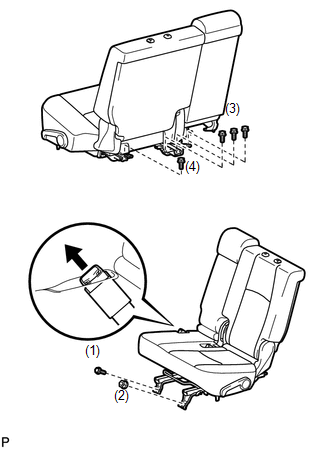
6. REMOVE REAR SEAT ASSEMBLY LH

(a) Disconnect the center inner seat belt from the seat.
(b) Remove the 5 bolts, nut and seat.
NOTICE:
Be careful not to damage the vehicle body.
HINT:
Be sure to remove the seat with the seatback folded down.
Installation
INSTALLATION
CAUTION / NOTICE / HINT
CAUTION:
Wear protective gloves. Sharp areas on the parts may injure your hands.
PROCEDURE
1. INSTALL REAR SEAT ASSEMBLY LH
(a) Place the seat in the cabin.
NOTICE:
Be careful not to damage the vehicle body.
HINT:
Be sure to install the seat with the seatback folded down.
(b) Connect the center inner belt to the seat.
(c) Temporarily install the seat with the 5 bolts and nut.
(d) Tighten the bolts and nut in the order indicated in the illustration.
Torque:
37 N·m {377 kgf·cm, 27 ft·lbf}
2. INSTALL REAR SEAT TRACK COVER LH

(a) Attach the 3 clips to install the cover.
3. INSTALL SEAT TRACK INNER BRACKET COVER LH
.png)
(a) Attach the 6 clips to install the cover.
4. INSTALL REAR SEAT TRACK OUTER BRACKET COVER

(a) Move the cover in the direction of the arrow to attach the 2 guides.
(b) Attach the 2 claws to install the cover.
5. INSTALL REAR SEAT TRACK INNER BRACKET COVER

(a) Attach the 2 claws and guide to install the cover.
6. INSTALL REAR SEAT HEADREST ASSEMBLY
(a) Install the headrest.
 Installation
INSTALLATION
CAUTION / NOTICE / HINT
CAUTION:
Wear protective gloves. Sharp areas on the parts may injure your hands.
HINT:
A bolt without a torque specification is shown in the standard bolt cha ...

Other materials about Toyota 4Runner:
Disassembly
DISASSEMBLY
PROCEDURE
1. REMOVE SHIFT LEVER CAP
2. REMOVE POSITION INDICATOR HOUSING ASSEMBLY
(a) Detach the 4 claws and remove the floor shift position indicator
housing.
3. REMOVE INDICATOR LIGHT ...
Fail-safe Chart
FAIL-SAFE CHART
1. FAIL-SAFE FUNCTION
(a) If the stabilizer control ECU detects a malfunction, the fail-safe functions
shown in the table below operate.
Malfunction Item
Fail-safe Function
Speed Sensor
KDS ...

0.0069