Toyota 4Runner: Security Horn Assembly
Components
COMPONENTS
ILLUSTRATION

Removal
REMOVAL
PROCEDURE
1. REMOVE AIR CLEANER CAP AND HOSE
.gif)
2. REMOVE AIR CLEANER CASE SUB-ASSEMBLY
3. REMOVE SECURITY HORN ASSEMBLY
|
(a) Disconnect the connector. |
|
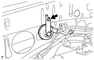
(b) Remove the bolt and horn.
Inspection
INSPECTION
PROCEDURE
1. INSPECT SECURITY HORN ASSEMBLY
(a) Apply battery voltage to the horn connector and check the operation of the horn.
OK:
|
Measurement Condition |
Specified Condition |
|---|---|
|
Battery positive (+) → Terminal 1 Battery negative (-) → Horn bracket |
Horn sounds |
If the result is not as specified, replace the security horn assembly.
Installation
INSTALLATION
PROCEDURE
1. INSTALL SECURITY HORN ASSEMBLY
(a) Install the horn with the bolt.
Torque:
5.5 N·m {56 kgf·cm, 49 in·lbf}
(b) Connect the connector.
2. INSTALL AIR CLEANER CASE SUB-ASSEMBLY
.gif)
3. INSTALL AIR CLEANER CAP AND HOSE
 Id Code Box
Components
COMPONENTS
ILLUSTRATION
Installation
INSTALLATION
PROCEDURE
1. INSTALL ID CODE BOX
(a) Attach the 2 claws and move the ID code box in the direction of the
arrow. ...
 Security Indicator Light Assembly
Components
COMPONENTS
ILLUSTRATION
Removal
REMOVAL
PROCEDURE
1. REMOVE NO. 2 INSTRUMENT CLUSTER FINISH PANEL GARNISH
2. REMOVE SECURITY INDICATOR LIGHT ASSEMBLY
(a) Pull th ...
Other materials about Toyota 4Runner:
Terminals Of Ecu
TERMINALS OF ECU
1. AIR CONDITIONING AMPLIFIER
(a) Measure the voltage and resistance according to the value(s) in the table
below.
Terminal No. (Symbol)
Wiring Color
Terminal Description
Condition
...
Slip Indicator Light does not Come ON
DESCRIPTION
Refer to Slip Indicator Light Remains ON (See page
).
WIRING DIAGRAM
Refer to Slip Indicator Light Remains ON (See page
).
CAUTION / NOTICE / HINT
NOTICE:
When replacing the master cylinder solenoid, perform calibration (See page
).
PR ...

0.0259