Toyota 4Runner: Television Camera(for Rear)
Components
COMPONENTS
ILLUSTRATION

Removal
REMOVAL
PROCEDURE
1. REMOVE ASSIST STRAP HOLE COVER
.gif)
2. REMOVE ASSIST STRAP ASSEMBLY
3. REMOVE BACK DOOR TRIM PANEL ASSEMBLY
4. REMOVE MULTIPLEX NETWORK DOOR ECU
5. REMOVE NO. 2 BACK DOOR SERVICE HOLE COVER
6. REMOVE BACK DOOR LOCK CYLINDER (w/o Smart Key System)
7. REMOVE BACK DOOR OUTSIDE GARNISH
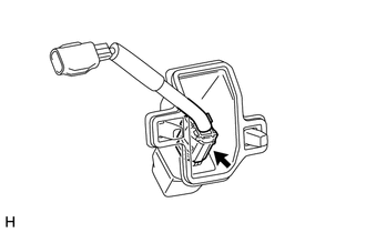
8. REMOVE REAR TELEVISION CAMERA ASSEMBLY
|
(a) Remove the 2 screws. |
|

|
(b) Disconnect the connector. |
|

(c) Detach the 2 claws and remove the rear television camera assembly.
9. REMOVE NO. 4 BACK DOOR WIRE
(a) Disconnect the connector and remove the No. 4 back door wire.
Installation
INSTALLATION
PROCEDURE
1. INSTALL NO. 4 BACK DOOR WIRE
(a) Connect the connector to install the No. 4 back door wire.
2. INSTALL REAR TELEVISION CAMERA ASSEMBLY
(a) Attach the 2 claws to install the rear television camera assembly.
(b) Connect the connector.
(c) Install the 2 screws.
3. INSTALL BACK DOOR OUTSIDE GARNISH
.gif)
4. INSTALL BACK DOOR LOCK CYLINDER (w/o Smart Key System)
5. INSTALL NO. 2 BACK DOOR SERVICE HOLE COVER
6. INSTALL MULTIPLEX NETWORK DOOR ECU
7. INSTALL BACK DOOR TRIM PANEL ASSEMBLY
8. INSTALL ASSIST STRAP ASSEMBLY
9. INSTALL ASSIST STRAP HOLE COVER
 Image from Camera for Rear View Monitor is Abnormal
DESCRIPTION
The display signal from the rear television camera assembly transmits to the
radio and display receiver assembly.
WIRING DIAGRAM
PROCEDURE
1.
CHECK HARNESS A ...
 Ultrasonic Sensor(for Front)
Components
COMPONENTS
ILLUSTRATION
ILLUSTRATION
Removal
REMOVAL
PROCEDURE
1. REMOVE UPPER RADIATOR SUPPORT SEAL
2. REMOVE FRONT BUMPER COVER
3. REMOVE NO. 2 ENGINE ROOM WIRE
...
Other materials about Toyota 4Runner:
Hood
Release the lock from the inside of the vehicle to open the hood.
Pull the hood release lever.
The hood will pop up slightly.
Push the auxiliary catch lever to the left and lift the hood.
CAUTION
Pre-driving check
Check that the hood is fully closed ...
Moon roof
Use the overhead switches to open and close the moon roof and tilt it up
and down.
Opening and closing
1. Opens the moon roof* The moon roof stops slightly before the fully open
position to reduce wind noise.
Press the switch again to fully open the m ...
0.0124