Toyota 4Runner: Lost Communication with A/C ECU (U0164)
DESCRIPTION
|
DTC Code |
DTC Detection Condition |
Trouble Area |
|---|---|---|
|
U0164 |
There is no communication from the air conditioning amplifier assembly. |
|
HINT:
For vehicles with a smart key system only.
WIRING DIAGRAM

CAUTION / NOTICE / HINT
NOTICE:
Inspect the fuses for circuits related to this system before performing the following inspection procedure.
HINT:
Operating the ignition switch, any switches or any doors triggers related ECU and sensor communication with the CAN, which causes resistance variation.
PROCEDURE
|
1. |
DISCONNECT CABLE FROM NEGATIVE BATTERY TERMINAL |
(a) Disconnect the cable from the negative (-) battery terminal before measuring the resistances of the main wire and branch wire.
CAUTION:
Wait at least 90 seconds after disconnecting the cable from the negative (-) battery terminal to disable the SRS system.
NOTICE:
When disconnecting the cable, some systems need to be initialized after the cable
is reconnected (See page .gif) ).
).
|
.gif)
|
2. |
CHECK FOR OPEN IN CAN BUS WIRE (AIR CONDITIONING AMPLIFIER ASSEMBLY BRANCH WIRE) |
|
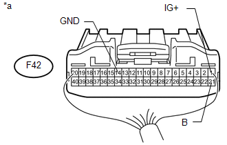
(a) Disconnect the F42 air conditioning amplifier assembly connector. |
|

(b) Measure the resistance according to the value(s) in the table below.
Standard Resistance:
|
Tester Connection |
Switch Condition |
Specified Condition |
|---|---|---|
|
F42-11 (CANH) - F42-12 (CANL) |
Ignition switch off |
54 to 64 Ω |
|
*a |
Rear view of wire harness connector (to Air Conditioning Amplifier Assembly) |
| NG | .gif) |
REPAIR OR REPLACE AIR CONDITIONING AMPLIFIER ASSEMBLY BRANCH WIRE OR CONNECTOR (CANH, CANL) |
|
|
3. |
CHECK HARNESS AND CONNECTOR (AIR CONDITIONING AMPLIFIER ASSEMBLY - BATTERY AND BODY GROUND) |
|
(a) Connect the cable to the negative (-) battery terminal. NOTICE: When disconnecting the cable, some systems need to be initialized after
the cable is reconnected (See page |
|
(b) Measure the resistance according to the value(s) in the table below.
Standard Resistance:
|
Tester Connection |
Condition |
Specified Condition |
|---|---|---|
|
F42-14 (GND) - Body ground |
Always |
Below 1 Ω |
(c) Measure the voltage according to the value(s) in the table below.
Standard Voltage:
|
Tester Connection |
Switch Condition |
Specified Condition |
|---|---|---|
|
F42-21 (B) - Body ground |
Always |
11 to 14 V |
|
F42-1 (IG+) - Body ground |
Ignition switch ON |
11 to 14 V |
|
*a |
Rear view of wire harness connector (to Air Conditioning Amplifier Assembly) |
| OK | |
REPLACE AIR CONDITIONING AMPLIFIER ASSEMBLY |
| NG | |
REPAIR OR REPLACE HARNESS OR CONNECTOR |
 Lost Communication with "Seat Control Module A" (U0208)
DESCRIPTION
DTC Code
DTC Detection Condition
Trouble Area
U0208
There is no communication from the front power seat switch LH.
...
 Brake Actuator (Skid Control ECU) Communication Stop Mode
DESCRIPTION
Detection Item
Symptom
Trouble Area
Brake Actuator (Skid Control ECU) Communication Stop Mode
Either condition is met:
...
Other materials about Toyota 4Runner:
If the vehicle becomes stuck
Carry out the following procedures if the tires spin or the vehicle
becomes stuck in mud, dirt or snow:
Stop the engine. Set the parking
brake and shift the shift lever to P.
Remove the mud, snow or sand
from around the stuck tire.
Place wood, ston ...
Terminals Of Ecu
TERMINALS OF ECU
1. CHECK COMBINATION METER ASSEMBLY
(a) Disconnect the F14 combination meter assembly connector.
(b) Measure the resistance and voltage according to the value(s) in the table
below.
Terminal No. (Symbol)
Wiring Co ...
0.0263