Toyota 4Runner: Transfer Case Rear Oil Seal
Components
COMPONENTS
ILLUSTRATION

Replacement
REPLACEMENT
PROCEDURE
1. DRAIN TRANSFER OIL
.gif)
2. REMOVE REAR PROPELLER SHAFT ASSEMBLY
(a) Remove the rear propeller shaft (See page
).
3. REMOVE REAR OUTPUT SHAFT COMPANION FLANGE SUB-ASSEMBLY
4. REMOVE REAR TRANSFER OUTPUT SHAFT COMPANION FLANGE OIL SEAL
5. REMOVE TRANSFER CASE REAR OIL SEAL
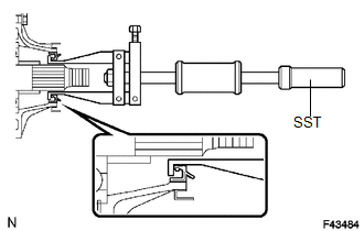
(a) Using SST, tap out the oil seal.
SST: 09308-00010
NOTICE:
Be careful not to damage the oil seal and rear case contact surface.
6. INSTALL TRANSFER CASE REAR OIL SEAL

(a) Coat the lip of a new oil seal with MP grease.
(b) Using SST and a hammer, tap in the oil seal until its surface is flush with the case upper surface.
SST: 09223-46011
SST: 09631-32020
7. INSTALL REAR TRANSFER OUTPUT SHAFT COMPANION FLANGE OIL SEAL
8. INSTALL REAR OUTPUT SHAFT COMPANION FLANGE SUB-ASSEMBLY
9. INSTALL PROPELLER SHAFT ASSEMBLY
(a) Install the rear propeller shaft (See page
).
10. ADD TRANSFER OIL
11. CHECK FOR TRANSFER OIL LEAK
 Transfer Case Front Oil Seal
Components
COMPONENTS
ILLUSTRATION
Replacement
REPLACEMENT
PROCEDURE
1. DRAIN TRANSFER OIL
2. REMOVE FRONT PROPELLER SHAFT ASSEMBLY
(a) Remove the front propeller shaft (See page
). ...
 Transfer Indicator Switch
Components
COMPONENTS
ILLUSTRATION
Inspection
INSPECTION
PROCEDURE
1. INSPECT TRANSFER INDICATOR SWITCH (4WD POSITION)
(a) Measure the resistance according to the value(s) in the table ...
Other materials about Toyota 4Runner:
Terminals Of Ecu
TERMINALS OF ECU
1. CHECK CLEARANCE WARNING ECU
(a) Disconnect the F95 clearance warning ECU assembly connector.
(b) Measure the voltage and resistance according to the value(s) in the table
below.
Terminal No. (Symbol)
Wiring Col ...
Portable Player cannot be Operated Using In-vehicle Device or Track Information
is not Displayed on In-vehicle Device
PROCEDURE
1.
CHECK USING ANOTHER "Bluetooth" AUDIO COMPATIBLE VEHICLE OF SAME MODEL
(a) Check if track information is displayed normally on another "Bluetooth" audio
compatible vehicle of the same model.
...
0.0088